Machinery Building Instructions Page 4
In order to build the machinery pieces shown here, you will need 15 castings each of molds 326 and 327.
 |
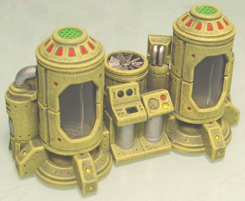
 Com Station |
 Ventilation Pump |
 Cryo Tubes |
 Power Coupling |
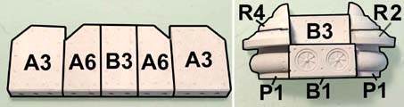
 Flight Deck |
 |
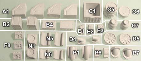
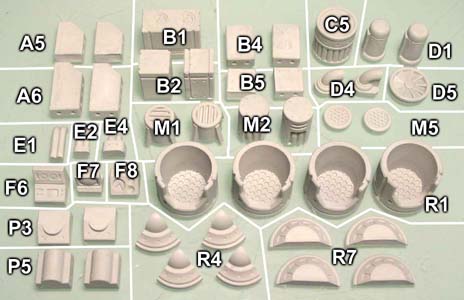
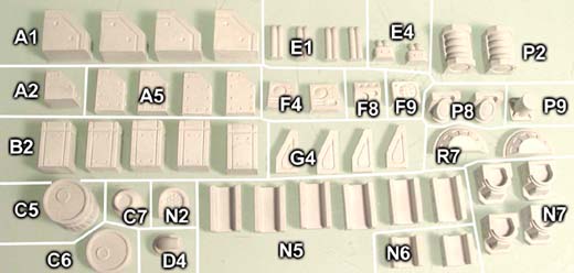
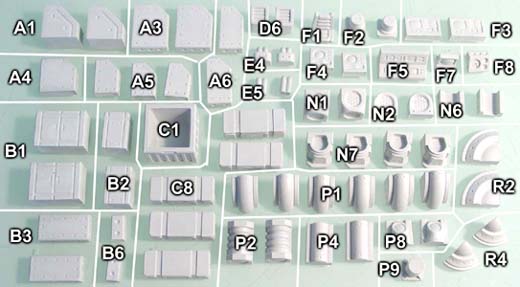
You can find an easily printable parts chart which includes pictures of each piece labeled on our Printed Plans page. Look for the item labeled "Machinery Parts List".
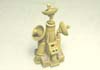
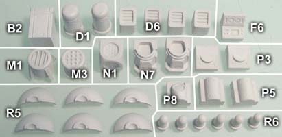
Com Station
| 1. | Parts List
|
 |
|---|
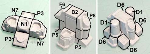
| 2. | Glue the five pieces in the first photo to form the base. It doesn't matter which way the N1 piece is facing. Add the pieces in the second photo. In the third photo, add the D6 pieces all the way around. |
 |
|---|
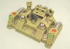
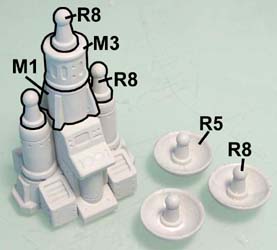
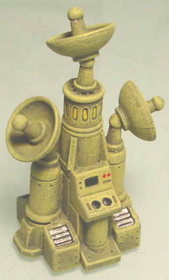
| 3. | Finish the com station by adding the M1 and M3 pieces onto the center. The R6 pieces go on all three high points. Also assemble three dishes as shown but do not glue them on until the whole piece has been painted. In the second photo is the completed com station. Click on it for a larger view. |
 |
 |
|---|
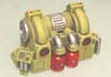
Ventilation Pump
| 1. | Parts List
|
 |
|---|
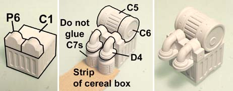
| 2. | Start with an upside down crate and add the P6 pieces on top. If you want removable canisters, place a piece of cereal box down under them and do not glue the canisters. Glue the hoses and barrel to the crate only. Remove the canisters after it's dry. |
 |
|---|
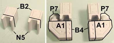
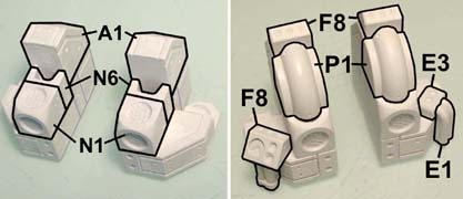
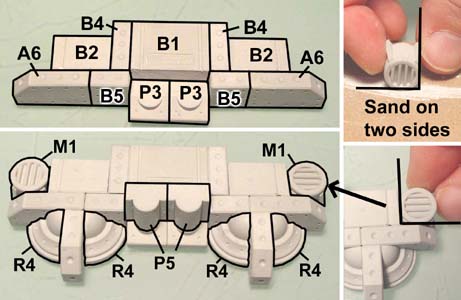
| 3. | Next we will make two side pieces. These will be mirror images of each other. Stand up the B2 pieces and glue the N5 pieces onto them. Then glue the additional pieces. Be sure the B4 pieces are flush with the side of the blocks you are gluing to. |
 |
|---|
| 4. | Continue to glue the additional pieces as shown. Cap off these pieces with the P1 rounded pipe blocks and at the very top are two F8 pieces with their control panels facing away from you. On the lower section, add the conduit pieces and control panel. |
 |
|---|
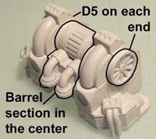
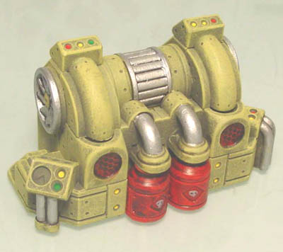
| 5. | Glue these two mirrored pieces on each side of the barrel section from step 2. Now glue the D5 decorative fan pieces on each end. Try to line up the D5 pieces with the barrel so it looks like they are an extension of the barrel. Click on the photo for a larger view. I did not glue the canisters on the front so they could be removed as part of a mission. |
 |
 |
|---|
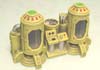
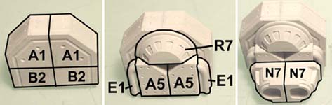
Cryo Tubes
| 1. | Parts List
|
 |
|---|
| 2. | The base of the cryo tubes use the blocks as shown. The only pieces you will have a little trouble fitting are the M1 pieces. These are supposed to tuck into the two corners. However, their fins prevent the circular part from setting against the sides of the corner. To fix this, you will need to sand the two corners of the M1 piece. |
 |
|---|
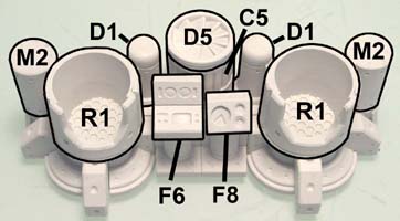
| 3. | Decorative pieces are added onto the base. Start by gluing the R1 tube pieces down first. Then add the M2 pieces directly on top of the M1 pieces. Slide the R1 tube pieces to touch against these. Add the D1 pieces so the flat strip is glued against the R1 tube pieces. In the center is a C5 piece positioned so the scraped side is facing up. Then top it with a D5 piece. |
 |
|---|
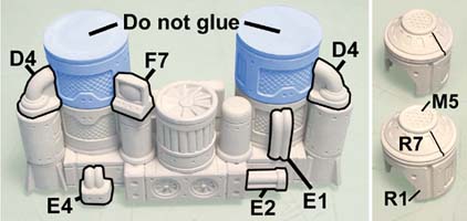
| 4. | Place a couple of R1 pieces on top of the existing ones but do not glue them down. Glue the D4 pieces on each side so it looks like the hoses are going into the R1 pieces but don't glue them to the R1 pieces. Add the other decorative pieces as shown. Glue together two cryo tops using the R1, R7 and M5 pieces. |
 |
|---|
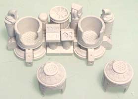
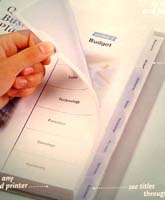
| 5. | Here are the final pieces before painting. For the clear plastic windows I am using plastic notebook dividers. These dividers are clear, fairly stiff but you can still easily cut them with scissors. This particular brand is Wilson Jones 8 tab transparent dividers #W55068. |
 |
 |
|---|
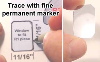
| 6. | On the machinery parts list, I have added a little template for the window of the R1 piece. You can find this parts list on our Printed Plans page labeled "Machinery Parts List". On page 2 of the parts list, locate the window template on the bottom left. Lay a clear plastic divider over it and draw around it with a fine tipped permanent marker. Cut it out with scissors and you should have a clear window the correct size to fit into the tube piece. |
 |
|---|
| 7. |
Bend the plastic and slide it into the groove. If the plastic bows too much and the bottom won't fit in, then trim some plastic off of the sides. If the plastic doesn't need to bend to fit into the groove, then it was cut too small and you will need to cut a new piece a little wider. Once it does fit, slide the other R1 piece over the other half of the window. If the two R1 pieces cannot meet, then the plastic window is too long and needs to be trimmed down. |
|---|
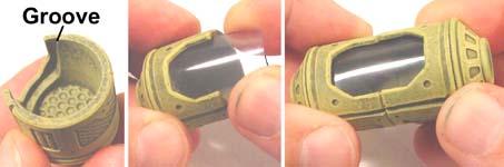 You will want to test fit the window before you glue the halves of the R1 pieces together. You can use any spare R1 pieces to do this.
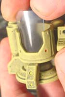
| 8. | Once dry, insert the clear plastic window into the tube half with the decorative insert in it. Place a small amount of glue on the other tube half (where they would meet). Slide the clear window into the other half until the two tube halves meet and are glued together. Click on the photo for a larger view. |
 |
 |
|---|
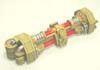
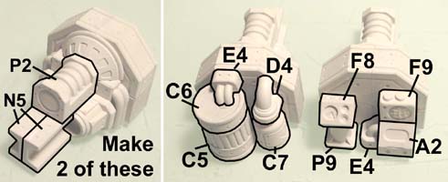
Power Coupling
| 1. | Parts List
|
 |
|---|
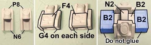
| 2. | The center section starts with these pieces. Position the F4 pieces so the thick edge is towards you. In the last photo, do not glue the B2 pieces shown in blue. |
 |
|---|
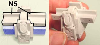
| 3. | Glue the N5 pieces to the center N2 piece. Do not glue it to the B2 pieces shown in blue. Once it's dry, remove the B2 pieces to reveal the piece you see here. |
 |
|---|
| 4. | We will end up needing 2 of these pieces. I'll just show you how to make one to save photo space. Glue the blocks together as shown. |
 |
|---|
| 5. | Center the N5 and P2 pieces on the end. Make 2 of these pieces. Now we will decorate the back sides of these pieces differently. The E4 piece on the barrel will fit better if you make the hoses go down into the spout on the top of the barrel. |
 |
|---|
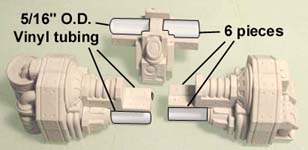
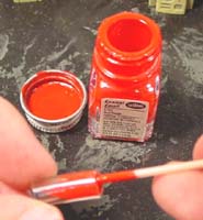
| 6. | You will need to paint these pieces before you add the tubing. I am using 5/16" O.D. vinyl tubing. Slide the tubing into each of the 6 channels and cut it the proper length using a hobby knife. |
 |
 |
|---|
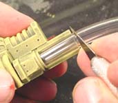
| 7. | Test fit the pieces together before you paint the insides of the tubing. The only paint that will stick to this tubing is enamel plastic model paint. This is a common oil based paint used to paint model cars with. You can find it any place that sells model car kits. To paint the tubing, stick a toothpick in the bottle and slide it inside the tubing. Move it around to paint the inside of the tubing. Feel free to experiment with different colors or blends of color inside the tube. |
 |
|---|
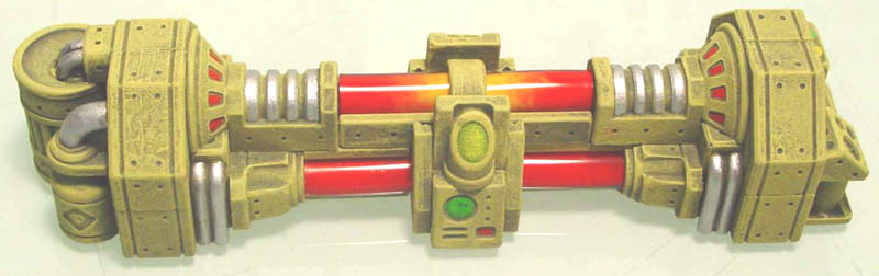
| 8. | Once dry, glue the vinyl tubing into the channels and glue the whole unit together. Here is a photo of the finished power coupling. Click on the photo for a larger view. |
 |
|---|
Flight Deck
| 1. | Parts List
|
 |
|---|
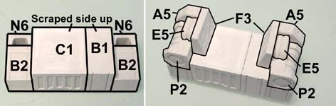
| 2. | Start by making the base. The C1 crate piece and B1 cabinet are placed scraped side up. Since these scraped sides will actually form the floor of the deck, you may want to sand them smooth. |
 |
|---|
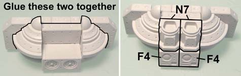
| 3. | These two pieces will glue together to form the front part of the flight deck. |
 |
|---|
| 4. | Glue the two assembled pieces (from the step above) together. Add the F4 and N7 pieces onto the front. |
 |
|---|
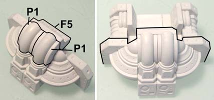
| 5. | Add the P1 pipe pieces in the gap between the R4 pieces. On the back side of the P1 pieces, glue an F5 control panel. Now glue the assembly from step 2 (above) onto the back of it. |
 |
|---|
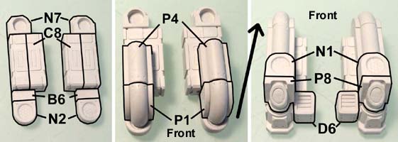
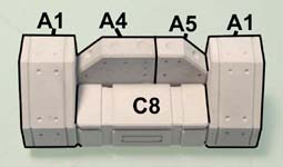
| 6. | Glue the crates together bottom to bottom. Add the other pieces on top, aligning them to the outside edges of the crates. In the last photo, the other end is facing towards you. |
 |
|---|
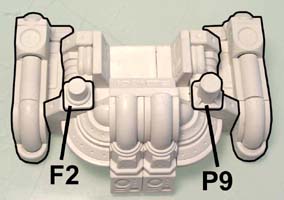
| 7. | Glue these two new pieces onto each side of the main unit. Add the F2 and P9 pieces on top. Assemble the front step as shown. |
 |
 |
|---|
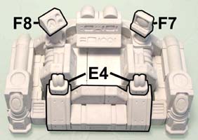
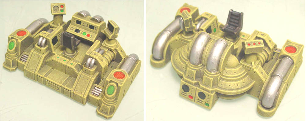
| 8. |
Add the front piece (built in the step above) onto the front of the main unit. Don't forget to add the E4 pieces onto the front step. Also glue the control panel and computer screen onto the top of the posts. Angle these so they can be easily seen by the pilot. |
 |
|---|
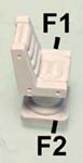 Glue one chair together but do not glue it down.
| 9. | Here are photos of the finished flight deck. I glued the chair into position after it was painted. Click on the photo for a larger view. |
 |
|---|