Machinery Building Instructions Page 5
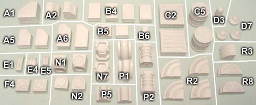
In order to build the machinery pieces shown here, you will need 15 castings each of molds 326 and 327.
 |
 Teleport Pad |
 Power Converter |
 Hover Buggy |
 Finished Photos |
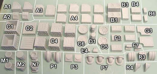
You can find an easily printable parts chart which includes pictures of each piece labeled on our Printed Plans page. Look for the item labeled "Machinery Parts List".
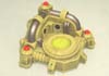
Teleport Pad
| 1. | Parts List
|
 |
|---|
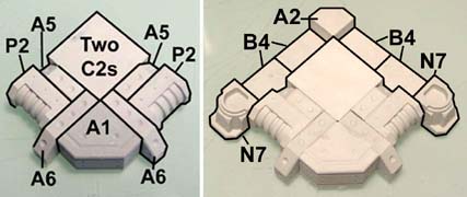
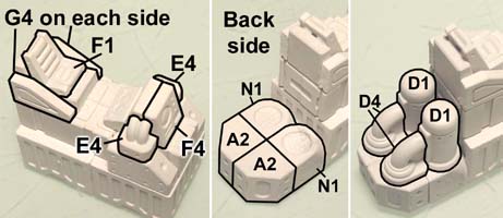
| 2. | In the first photo, you will want to stack the two C2 pieces so that the scraped side is facing up. Be sure that all of the A pieces have their angles facing upward. Glue the additional pieces around the outside. |
 |
|---|
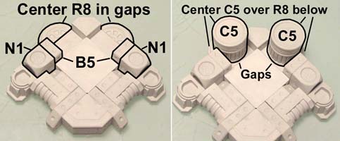
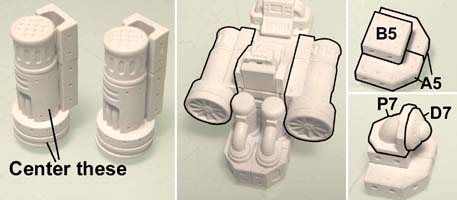
| 3. | The B5 pieces are standing on end. Once the N1 and B5 pieces are glued into place, you will notice a large gap on each side. Center the R8 half circles in front of each large gap. Now glue a C5 barrel centered over each R8 half circle. This will leave a small gap between the C5 barrel and the large block in the center. |
 |
|---|
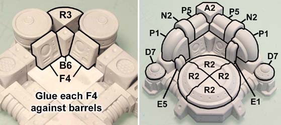
| 4. | Add the pieces to the inside. The F4 pieces should touch against the barrels. Now add the rest of the pieces. The E5 conduit drops down into the gap but the E1 conduit piece does not. |
 |
|---|
| 5. | Finish the teleporter pad by adding the final decorative pieces. This is all one piece to be painted. Click on the second photo for a larger version. |
 |
 |
|---|
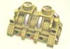
Power Converter
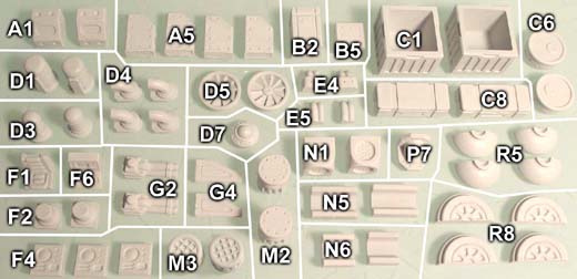
| 1. | Parts List
|
 |
|---|
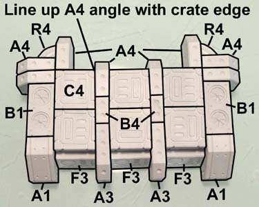
| 2. | Start with the C4 crates and glue the A and B pieces between them. All of the A pieces have their angles facing outward. The B4 pieces in the center are standing on end. Be sure the outside angle of the top center A4 pieces aligns with the edge of the C4 crates. The bottom A3 pieces will protrude out of the front. The top left and right corners have R4 pieces glued in them. The B1 pieces are placed fans facing upwards. The F3 pieces along the front bottom are placed thick edge down. |
 |
|---|
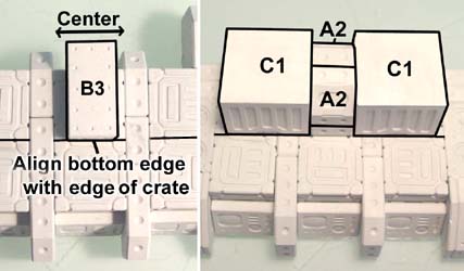
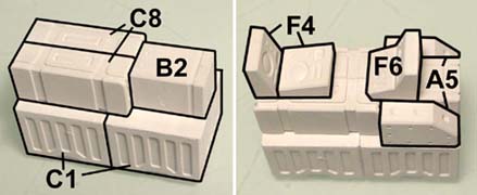
| 3. | Glue a B3 block on the top center of this assembly. Be sure that the bottom edge of this block lines up with the center joint between the two crates. Also be sure it is centered side to side. The back will hang over. Glue the A2 pieces on top of this block, angles facing outward. Then glue the two C1 crates upside down onto each side. The bottom edge of these C1 crates will also line up with the center seam in the crates below. The far side of these crates will hang over the back side. |
 |
|---|
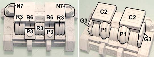
| 4. | Glue the decorative pieces around the large crates. The B6 small blocks tuck behind the P3 blocks. The back of the G3 slabs rest against the N7 pieces. The ridges of the C2 crate tops should go the same direction. |
 |
|---|
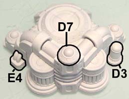
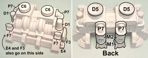
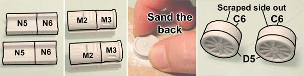
| 5. | Center the C6 pieces on top of the crates scraped side up. Add the other decorative bits. Turn the piece around and glue the additional pieces onto the back side. The M1 pieces will glue against the A4 blocks protruding from the back side. |
 |
|---|
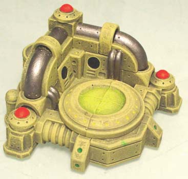
| 6. | Here is the completed power converter. This is all one piece to be painted. Click on the photo for a larger version. |
 |
|---|
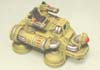
Hover Buggy
| 1. | Parts List
|
 |
|---|
| 2. | The main body is made using the crate pieces. Be sure the C8 crates are glued "scraped side together". Center the C8 crates to leave an equal gap on the left and right. Add the decorative pieces. The F6 piece is a little tricky. Just try to position it as close to the photo as possible. |
 |
|---|
| 3. | Glue the seat and decorative pieces on top. Turn the piece around and glue these onto the back side of it. |
 |
|---|
| 4. | Now for the engines. Sand the backs of the C6 pieces. Glue them scraped side facing outwards. |
 |
|---|
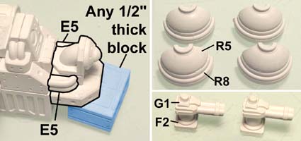
| 5. | Center the tubes onto the round bases with the bases facing smooth side up. These will fit onto each side of the body, right against the C8 crates. The far right on this photo shows how to build the nose of the buggy. |
 |
|---|
| 6. | Glue the piece from step 5 (above) to the front of the buggy. Use any 1/2" tall block to prop the nose up the correct height while gluing. Also add the E5 conduits onto each side of the nose section. Glue together four of the feet as shown. Also glue together two guns. |
 |
|---|
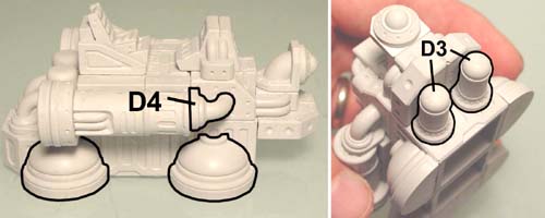
| 7. | Glue the feet on both sides of the buggy. Also add the P4 decorative pieces onto the engines on both sides of the buggy. Glue the D3 decorative pieces under the nose to help support it. Do not glue the two guns on until after the buggy is painted. |
 |
|---|
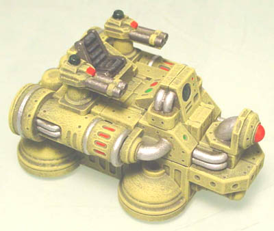
| 8. | Wait until the model is painted before you glue the guns onto the top of it. Click on the photo for a larger version. |
 |
|---|
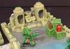
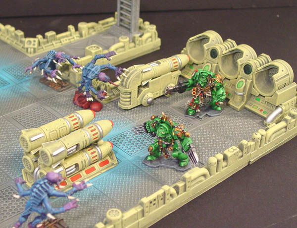
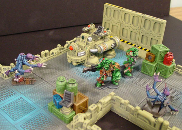
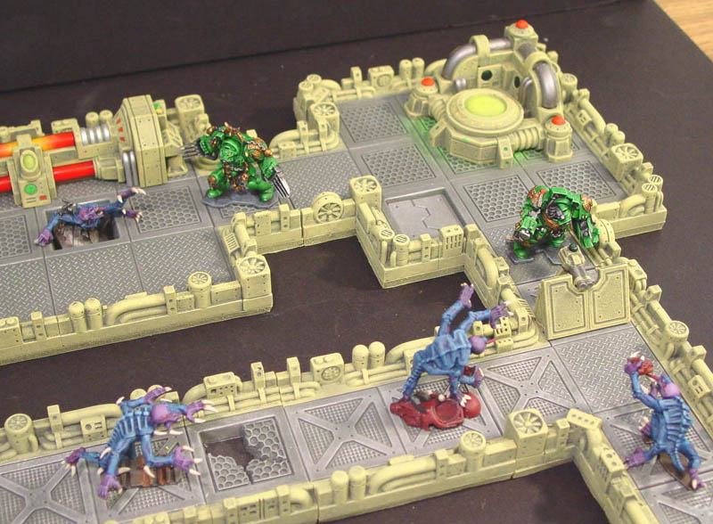
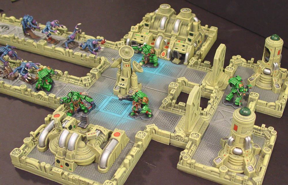
Finished Photos
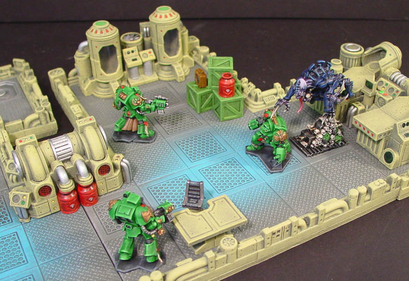
Below are finished photos of them used on a game board. Click on a photo to see a larger version of it. The models were produced by Games Workshop.
Hirst Arts is not affiliated with or endorsed by Games Workshop in any way.
 |
 |
 |
 |
 |
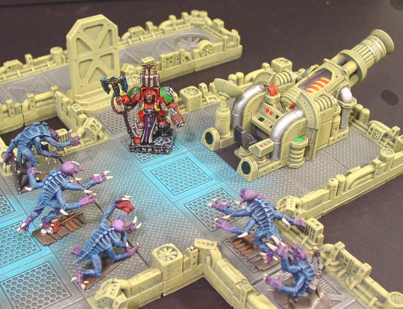 |
Terminators were painted by Greg Cymbalist - Distant Light Miniatures.
Genestealers were painted by Kris Marquardt.
The Brood Lord and Terminator Librarian were painted by Jeremy Spencer.